When the bar does not rotate, the tool has to do everything. A guide to insert selection, slide setup, and troubleshooting the most common problems on rotary-table transfer machines.
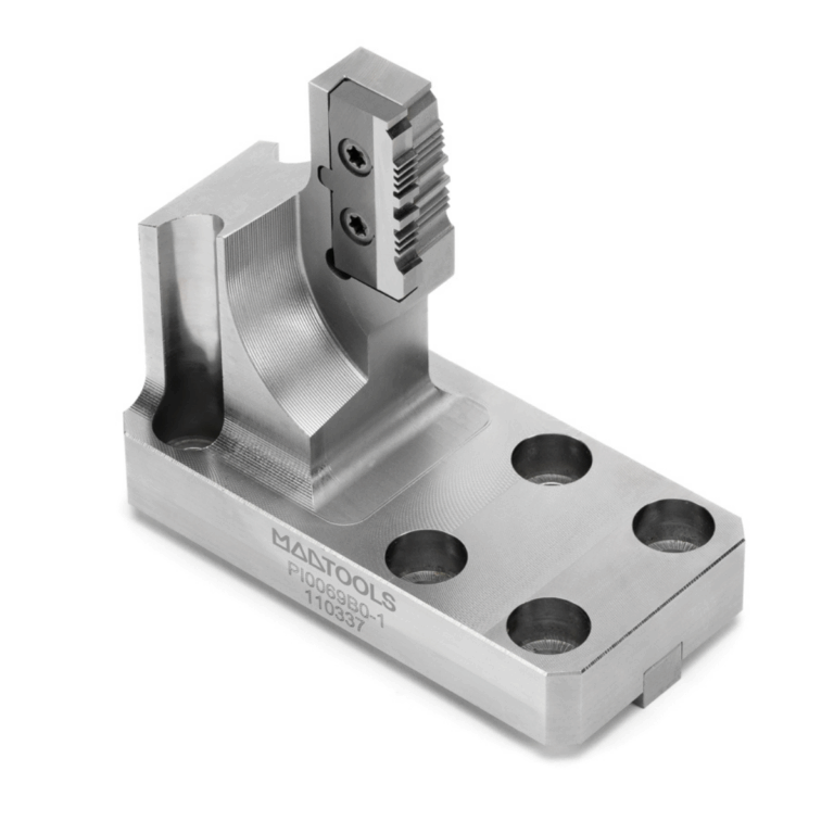
MadTools recessing slide with mechanically clamped carbide insert for static-bar transfer machines.
Why static turning is a world of its own
On rotary-table transfer machines with a static bar — Gnutti, BTB, DVK, Buffoli — turning works in reverse: the workpiece stays fixed in the collet, and a rotating head carries the insert around the part. This is the principle of so-called “static turning”, a term that Gnutti Transfer helped to popularise [1].
The heart of the operation is the recessing slide: a component that moves radially inside the rotating head and carries the mechanically clamped carbide insert. This slide must perform facing, recessing, contouring, and grooving operations while rotating at speeds typically between 1,000 and 4,000 rpm [2].
The problem: cutting conditions are very different from conventional turning. Centrifugal force acts on the insert and the slide, balancing becomes critical, chip space is limited, and coolant is delivered through rotating channels with reduced efficiency. Anyone who selects the insert as they would on a conventional CNC lathe will often find that the results do not add up.
What changes compared to conventional turning
The fundamental difference is kinematic: in conventional turning the workpiece rotates and the tool is stationary; in static turning on a transfer machine it is the other way round. The effect on the process is significant.
Centrifugal force on the insert. The centrifugal force F = m × r × ω², where m is the mass of the insert + slide, r is the distance from the axis of rotation, and ω is the angular velocity [3]. At 3,000 rpm, with a 200 g slide at 40 mm from the axis, the centrifugal force reaches approximately 79 N. This force tends to push the insert away from the axis and can loosen the clamping over time.
Mandatory balancing. The rotating head is intrinsically asymmetric: the slide protrudes on one side. According to ISO 1940-1, for rotating tools at medium speeds (1,000–4,000 rpm) at least grade G6.3 is required, but grade G2.5 is recommended for finishes below
Chip evacuation. In conventional turning, chips fall by gravity. On the rotating transfer, centrifugal force tends to throw chips away from the cutting zone — an advantage when it works. But long chips can wrap around the head, causing machine stoppages. Insert chip control becomes more critical than on a lathe.
| Parameter | Conventional lathe | Static-bar transfer |
| Rotating element | Workpiece (spindle) | Tool-holding head |
| Centrifugal forces | On the workpiece (negligible at low speeds) | On the slide + insert (critical) |
| Balancing | Not required below 3,000 rpm | Always required (asymmetric head) |
| Coolant | External, direct on the cutting zone | Through rotating channels (less efficient) |
| Chip evacuation | Falls by gravity | Centrifugal force throws chips away |
| Insert change | Machine stopped, direct access | Limited space, restricted access |
Table 1 — Kinematic and operational comparison between conventional turning and static turning on transfer machines. Sources: [1], [2], [4].
Insert selection criteria for recessing slides
On a conventional lathe, insert selection follows established rules. On the recessing slide of a transfer machine, specific adaptations are required.
Nose radius: smaller than on a lathe. The general rule is to select a nose radius equal to or smaller than the depth of cut [5]. On the transfer machine, where system rigidity is lower due to the translating slide, it is best to stay on the low side: radius 0.2–0.4 mm for finishing, 0.4–0.8 mm for semi-finishing. Excessively large radii increase the radial force component and amplify the vibrations already present due to imbalance.
Positive geometry, always. Negative inserts require higher cutting forces. On transfer machines, where the available power per station is limited and slide rigidity is lower than a fixed toolholder, positive geometry (rake angle > 0°) reduces forces and improves stability [5]. For brass, caution: a positive rake can cause “grabbing” — use geometries with rake close to 0° or inserts with a sharp cutting edge and no chipbreaker.
Mechanical clamping: the screw must overcome centrifugal force. The insert clamping system (screw, lever, wedge) must guarantee a clamping force greater than the centrifugal force acting on the insert during rotation. At every insert change, check the clamping screw torque with a torque wrench. On extended shifts, a mid-shift check is not paranoia: it is prevention.
| Workpiece material | Recommended insert shape | Nose radius (mm) | ISO grade | Coating |
| Brass CW614N | DCMT / CCMT (positive) | 0.2 – 0.4 | N (non-ferrous) | Uncoated or TiN |
| Lead-free brass | DCGT / CCGT (sharp) | 0.2 – 0.4 | N | Uncoated |
| Steel C40–C45 | DCMT / CCMT | 0.4 – 0.8 | P (steels) | CVD TiCN+Al₂O₃ |
| Stainless AISI 303/304 | DCMT (positive, sharp edge) | 0.4 | M (stainless) | PVD TiAlN |
| Aluminium 6082 | DCGT (positive, polished) | 0.4 – 0.8 | N | Uncoated (polished) |
Table 2 — Quick insert selection guide for recessing slides, by material. Sources: [5], [6].
Surface roughness: the formula still holds, but the context changes
Theoretical roughness in turning follows the well-known relationship Ra ≈ f² / (8 × r), where f is the feed per revolution and r is the insert nose radius [7]. This formula remains valid in static turning as well, because the cutting geometry does not change. What does change are the factors that cause the actual result to deviate from the theoretical value.
On transfer machines, vibrations from imbalance and the reduced stiffness of the slide worsen the finish compared to the calculated value. In practice, the actual Ra is typically 1.5–2 times the theoretical value. To achieve a specified finish, it is advisable to set parameters targeting a theoretical Ra equal to half the target value.
| Nose radius (mm) | Feed (mm/rev) | Theoretical Ra (µm) | Finish class |
| 0.2 | 0.05 | 1.56 | Fine finish |
| 0.4 | 0.08 | 2.00 | Medium finish |
| 0.4 | 0.12 | 4.50 | Semi-finishing |
| 0,8 | 0.15 | 3.52 | Medium finish |
| 0,8 | 0.20 | 6.25 | Semi-finishing |
Table 3 — Theoretical Ra roughness as a function of nose radius and feed. Formula: Ra = f² / (8 × r) × 1000 [µm]. Source: [7].
Practical rule: if the drawing requires Ra 3.2 µm, set feed and nose radius to achieve a theoretical Ra ≤ 1.6 µm. This margin absorbs vibrations and tool wear.
Recessing slide setup: the checklist that prevents stoppages
Setting up a recessing slide requires more care than a conventional toolholder. Every millimetre of imbalance is multiplied by the square of the angular velocity. Here are the critical steps:
- Clean the insert pocket and the slide seating surface. Chip residue or crystallised coolant will affect positioning.
- Mount the insert and tighten the screw to the torque specified by the manufacturer (typically 1.5–3 Nm for DCMT/CCMT inserts). Always use a torque wrench.
- Check the radial protrusion of the slide: it must correspond to the programmed depth of cut plus the expected stock allowance. Excessive protrusion worsens imbalance.
- Check the balance of the assembled head. If the machine does not have an integrated balancing system, use a calibrated counterweight in the position opposite the slide.
- Run a trial cut at reduced speed (50% of nominal) and verify surface finish and dimensions before bringing the machine up to full speed.
- Document the slide position and clamping torque. At the next setup, you will have a reliable starting point.
Troubleshooting: when something does not add up
Problems in static turning often have different causes from those on a conventional lathe. Centrifugal force is the hidden variable that comes into play in almost every anomaly.
| Symptom | Probable cause | Corrective action |
| Periodic vibration (chatter) | Head imbalance; nose radius too large relative to depth of cut | Check balancing (ISO 1940-1 G2.5); reduce nose radius; increase depth of cut to ≥ nose radius |
| Progressive dimensional drift | Insert flank wear; clamping screw loosened by centrifugal force | Check VB (limit 0.3 mm per ISO 3685); verify screw clamping torque at every shift; use medium-strength Loctite where permitted |
| Poor surface finish | Feed too high for nose radius; built-up edge (BUE) on stainless or aluminium | Reduce f to ≤ 2/3 of nose radius; increase Vc by 10–15%; switch to uncoated polished insert for aluminium |
| Long, stringy chips | Inadequate chipbreaker; centrifugal force interferes with chip breaking | Select geometry with more aggressive chipbreaker; increase feed; check coolant pressure (min. 30 bar) |
| Cutting edge chipping | Grade too hard; entry impact due to imbalance; variable depth of cut | Switch to a tougher grade (e.g. from P10 to P20); check balancing; verify workpiece concentricity in the collets |
| Insert shifting in the pocket | Insufficient clamping torque; centrifugal force exceeds clamping force; slide pocket worn | Check torque with a torque wrench; inspect pocket (flatness and cleanliness); at high speeds, consider a slide with reinforced or custom clamping |
Table 4 — Troubleshooting guide for static turning on transfer machines. Sources: [3], [4], [5], [8].
Conclusions
Static turning on transfer machines is not a minor variant of conventional turning. It is a process with its own rules, where centrifugal force conditions every aspect: from insert selection to clamping, from balancing to surface finish.
Three things to take to the shop floor on Monday morning: always check the insert screw clamping torque with a torque wrench; size nose radius and feed to achieve a theoretical Ra equal to half the value required on the drawing; check head balancing at every configuration change.
MadTools designs and manufactures recessing slides with mechanically clamped carbide inserts, optimised for the leading rotary-table transfer machines. When the standard slide does not solve the problem — due to space constraints, complex profiles, or tight tolerances — the MadTools technical department develops custom solutions starting from process analysis.
Sources and references
[1] Gnutti Transfer S.p.A. — “Macchine transfer per la lavorazione di particolari da barra”, Techmec.it, 2022. Description of the static turning process with non-rotating bar.
[2] Production Machining — “Road Trip to Gnutti Transfer”, 2020. Technical description of transfer configurations with rotating turning heads and indexable inserts.
[3] HAIMER GmbH — “Fundamentals of Tool Balancing”. Formula F = m × r × ω² and calculation of permissible residual unbalance (Uper).
[4] Sandvik Coromant — “Tool Balancing and RPM”. Reference to ISO 1940-1, balancing grades G2.5 and G6.3, and ISO 16084 standard for rotating tools.
[5] Sandvik Coromant — “How to Choose Correct Turning Insert”. Insert shape selection criteria, nose radius ≤ depth of cut, positive vs negative geometries.
[6] Mitsubishi Materials Corporation — “Formula for Turning”. Formula h = f² / (8 × RE) for theoretical roughness, with numerical example.
[7] Machining Doctor — “Surface Finish Calculators, Convertors, and Charts”. Formula Ra = f² / (8 × r), relationship between halving the feed and 4× improvement in finish.
[8] ISO 3685:1993 — “Tool-life Testing with Single-point Turning Tools”. Insert end-of-life criterion: VB = 0.3 mm (uniform flank wear).
[9] Production Machining — “Beyond One and Done”, 2022. Data on BTB configuration with recessing heads and quality control on CNC transfer machines.
[10] Big Daishowa — “Demystifying Insert Nose Radius Selection”. Practical rule: radial depth of cut between 1/2 and 2/3 of the nose radius to avoid chatter.